

Supervisors
 |
 |
|
Professor Mahmoud Shariati |
Professor Khalil Farhangdoost |
Head of Laboratory & Site Manager
 |
 |
|
Kamal kolasangiani
|
Reza Karimi
|
Introduction to Fatigue
Fatigue may occur when a member is subjected to repeated cyclic loadings (due to action of fluctuating). The fatigue phenomenon shows itself in the form of cracks developing at specific locations in the structures. Structures subjected to repeated cyclic loadings can undergo progressive damage which shows itself by the propagation of cracks. This damage is called fatigue and is represented by a loss of resistance with time. Fatigue testing is defined as the process of progressive localized permanent structural change occurring in a material subjected to conditions that produce fluctuating stresses and strains at some point or points and that may culminate in cracks or complete fracture after a sufficient number of fluctuations.
The Goal of Fatigue Test
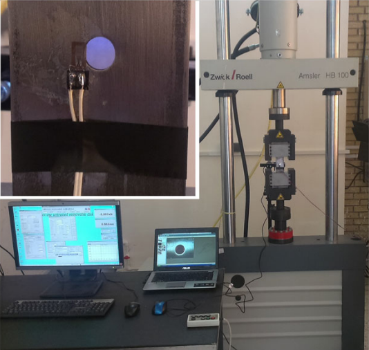
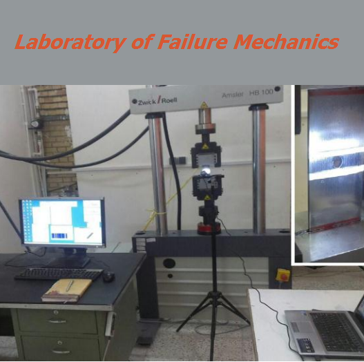
It is important to experimentally investigate on mechanical parts in order to evaluate their behavior under different loading conditions such as monotonic, cyclic, overload, impact and multi-axial one. The goal of fatigue and fracture laboratory is to study on fatigue life of standard and non-standard mechanical parts and specimens to achieve their fatigue life and S-N curves.
The other significant end of this research laboratory is to measure different parameters that are useful for understanding the fracture properties of materials which are beneficial to be applied in finite element modeling.
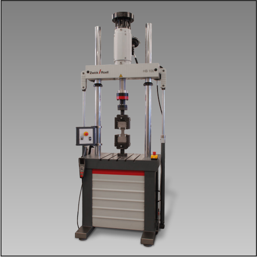
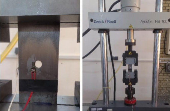
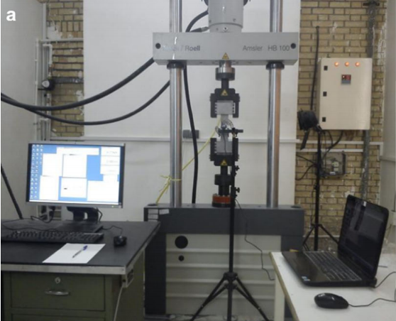
Servo-Hydraulic Testing Machines Zwick/Rowell HB100
HB servo-hydraulic testing machines have the testing actuator mounted on the upper crosshead. This makes them extremely versatile in use, especially the version with integrated T-slotted platform, enabling flexure tests and component testing in addition to standard fatigue tests. The load cell can be attached to the lower cross‐ head or directly to the piston rod, depending on the application.
Description of Operation
These 2-column load frames are designed for materials and component testing under dynamic loading in a closed force-flow. The frame is supported on vibrationisolating leveling units so that no appreciable forces are transmitted to the floor during normal operation. Where tests or environmental conditions are critical in nature, the use of optionally available air-springs is advisable; these have a natural frequency of approximately 3 - 6 Hz.
The efficiency of the testing system is enhanced by the especially high axial and lateral stiffness of the HB load frames, enabling higher frequencies and specimen deformations Moreover, high lateral forces which may occur in compression and flexure tests can be absorbed without difficulty.
The frames also feature extremely precise alignment; Following installation of the testing actuator and load cell, alignment accuracy is +0.1 mm per meter separa‐ tion; at distances below 350mm the offset is constant at 0.05mm. Plane-parallelity of mounting surfaces is equal to or better than 0.03 mm per 100 mm. All fixtures and ZwickRoell load cells are mounted via flanges with centering-spigot.
Advantages and Features
• testing actuator mounted on upper crosshead
• convenient working height
• hydraulic clamping and adjustment for easy posi‐ tioning of upper crosshead
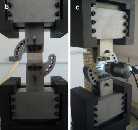
• comprehensive range of accessories, including hydraulic grips, compression platens, flexure test kit etc.
• safety housing for compliance with CE Machinery Directive
• version with integrated T-slotted specimen ideal for fatigue tests on components